This article examines - primarily from a technical point of view - the alleged development of "Reichsflugscheiben" ("Nazi-UFOs") by the (alleged) German engineers Schriever, Habermohl, Miethe, the Italian Giuseppe Belluzo[1], and the (allegedly) associated construction activities of the German engineer J. Andreas Epp.
Epp was said to have been inspired to design a flying saucer by a flight demonstration of the experimental helicopter "Focke-Wulf Fw 61"[2] in 1938.[3]
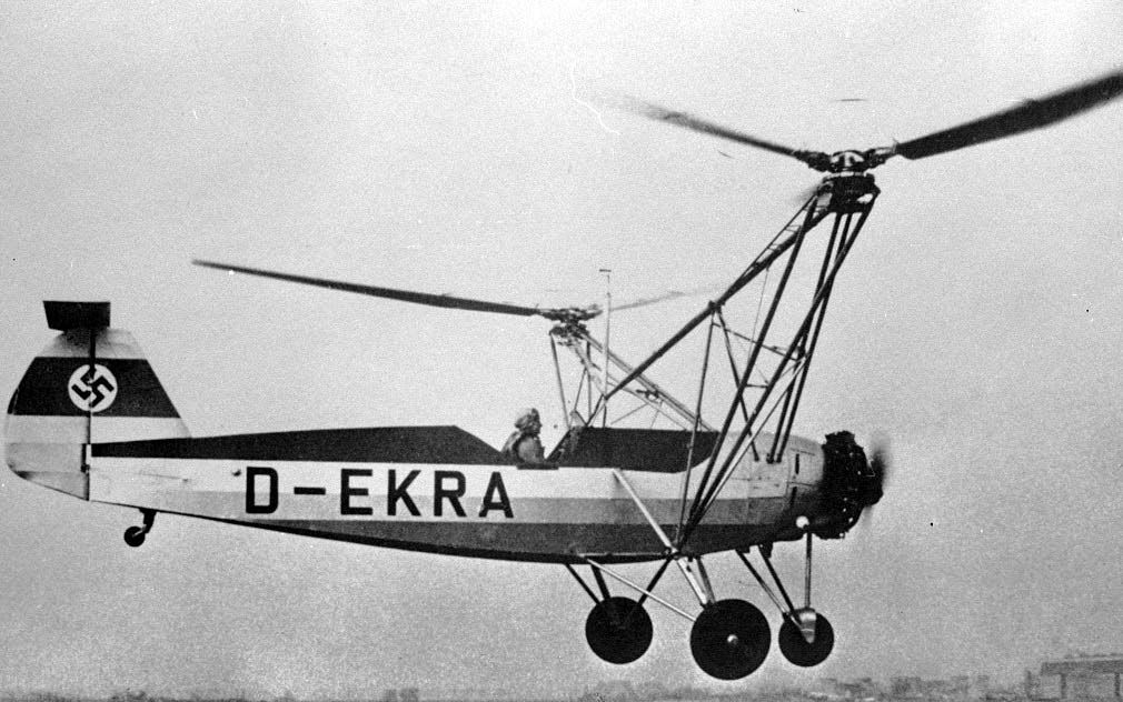
Picture 1: Hanna Reitsch flies the "Fw 61 V2"
Indeed Epp did create a total of 4 design drawings;all of which equipped with a main rotor, with their airframes in their centres. - Epp is said to have dealt with with the construction of flying discs for the first time from 1939 to 1942 and he states to have built an airworthy model in 1940.[4]

Picture. 2: Epps design drawing of his first flying saucer; the rotor is being operated by two jet engines integrated in the edge of the rotor. (Epp: 2005, p 79)
Furthermore Epp claims to have handed over the model of the flying disc to the "Reichsluftfahrtministerium" (Ministry of Aviation) in Berlin in 1941. The Chief of the Technical Office of the Reichsluftfahrtministerium (in short, RLM), General Ernst Udet, in turn, is said to have forwarded it to General Dornberger, who is said to have tested it at Peenemünde rocket test site. - Based on Epps draft another flying disc has then been designed, built and tested, by the engineers Habermohl and Schriever in Prague.[5]

Picture 3 Design drawing of a flying disc by Schriever and Habermohl, by Rudolf Lusar (Lusar: 1964, p 219.)
According to the article "Flying saucers" in Rudolf Lusars book "The German weapons and secret weapons of World War 2 and its further development" (5th edition, Munich 1964), the flying disc by Miethe and Belluzo (erroneously referred to as Bellonzo's by Epp and Lusar) have had a "disk-like" design, "with integrated adjustable nozzles."[6] The point whether there was a disk with the integrated nozzle rotating around an airframe in its centre, or whether the design was in fact an aircraft wing like the designs of Arthur Sack's,[7] was not dealt with by Epp.
Epp claims to have made another airworthy model in 1946 after the completion of a new construction. The main innovation compared to the previous model was a coaxial rotor as a main rotor.[8] There were said to have been more flight tests with a revised version in 1953/54 , followed by flight tests with a model of his last design, the "Omega Diskus 39/58" in 1958. [9]
Lift and propulsion were said to have been designed in Epps alleged, as well as in the construction by Schriever and Habermohl by a "Hubflächenring" (helicopter rotor) equipped with adjustable "Flügelscheiben" (rotor blades) rotating around an airframe in the centres. [10] The flying discs described were therefore designed as so-called "rotorcraft", which include, for example also the helicopter.[11] It is striking that in both drafts no rotor was provided as a torque balance, so that the airframe would have uncontrollably rotated around its own axis (Epp designed a coaxial rotor to compensate the torque only in the alleged construction from 1946)! - even the small rotor on the roof of the airframe of Epp's flying disc (see picture 2), was said to have not been planned to compensate the torque, but to speed up the air flow in order to reinforce the impact of the helicopter rotor.[12]
Epp and Lusar claim that the flying disc designed by Habermohl and Schriever had possessed almost twice the supersonic speed.[13] But for all rotorcrafts it needs to be pointed out, The top speed is limited by the aerodynamics of the rotor blades: The proceeding blade has, compared to the stream of air coming in from the front, a higher speed than the backward stream. If the proceeding rotor blade is now approaching at its outer edges the speed of sound, uplifting forces are bound to decrease; and there is a strong increase in resistance, and high stress of the rotor blade by torsional momentum. "[14]
Furthermore, the two authors disregard that the operating power of a rotorcraft - since both the power for the lifting-up as well as for forward flight are directed to the main rotor - is split in exactly two areas. Additionally, air resistance increases considerably during forward flight, because the entire aircraft has to be tilted in the direction of flight at a certain angle! [15]
If the circular flying disc would have served as a wing (supposedly designed and built by Miethe and Belluzo), it would have even been worse concerning the flight characteristics; the reason for this is founded in the extremely poor ratio of the span to the average wing depth; the induced resistance would be very large![16]
However, a service ceiling specified by Lusar and Epp of 12,400m for the flying saucer designed by Schriever and Habermohl[17] can indeed be achieved. On June 21st, 1972, a French helicopter reached for the first time an altitude of 12442m.[18]
Apart from the technical aspects of the alleged flying discs, however it is interesting that Epp by his own account was interrogated by American intelligence in the Intelligence Center of the US 7th Army in Freising, after he had been taken prisoner of war. [19] This statement is so interesting because there really is a now shared secret file about some Joseph Andreas Epp in the "National Archives" in the US.[20] It would be very interesting to know whether Epp was interrogated to his alleged developments in aircraft technology, especially because surveys concerning engineering projects were actually carried out by special units for "Technical Intelligence", and there is no corresponding report in the total output of all reports! [21]
Author: Christian Brandau - The text is available under the "Creative Commons Attribution 4.0 International (CC BY 4.0)".
References:
[1] https://de.wikipedia.org/wiki/Giuseppe_Belluzzo
[2] https://de.wikipedia.org/wiki/Focke-Wulf_Fw_61
[3] J. Andreas Epp: Die Realität der Flugscheiben, 2. Auflage, Peiting 2005, p. 75 - 76 and p. 83.
[4] ibid. p. 83.
[5] ibid. p. 79 and 82.
[6] Lusar, Rudolf: Die deutschen Waffen und Geheimwaffen des 2. Weltkrieges und ihre Weiterentwicklung, 5. edition, München 1964, p.220.
[7] https://de.wikipedia.org/wiki/Arthur_Sack
[8] Epp: 2005, p. 103 - 105.
[9] ibid. p. 118 - 130.
[10]
a) Epp: 2005 p. 83.
b) Lusar: 1964, p. 220.
[11] https://de.wikipedia.org/wiki/Drehflügler
[12] Epp: 2005 p. 84.
[13]
a) Epp: 2005 p. 96.
b) Lusar: 1964, p. 220.
[14] https://de.wikipedia.org/wiki/Hubschrauber
[15] Hubschrauber. In: Wie funktioniert das? - Die Technik im Leben von heute, 2. edition, Mannheim / Wien / Zürich 1978, p. 414.
[16] Tragflügelgeometrie. In: Wie funktioniert das? - Die Technik im Leben von heute, 2. edition, Mannheim / Wien / Zürich 1978, p. 396.
[17]
a) Epp: 2005 p. 96.
b) Lusar: 1964, p. 220.
[18] http://www.fai.org/fai-record-file/?recordId=754
[19] Epp: 2005 p.101.
[20] Epp, Joseph Andreas, U.S. Army Intelligence, Record Group 319, Box 186, File Number GE013347, The National Archives at College Park, College Park, Maryland. - http://www.archives.gov/iwg/declassified-records/rg-319-army-staff/personal-name-files-new.html
[21] Evaluation Reports (ER), Final Reports (FR) und Overall Reports der British Intelligence Subcommitee, Reports der Combined Intelligence Objectives Subcommitee (C.I.O.S.) und Field Intelligence Agency (F.I.A.T.).
Picturre credits:
Picture 1: https://commons.wikimedia.org/wiki/File:Fw_61_V.JPG - Lizenziert unter CC BY-SA 3.0 de über Wikimedia Commons
Picture 2: http://1.1.1.1/bmi/greyfalcon.us/pictures/epp123.gif - Embedded external work in accordance to ECJ judgment "C-348/13".
Abb. 3: http://1.1.1.4/bmi/2.bp.blogspot.com/-g7DWK0kLR7g/Tcv8cX6nwNI/AAAAAAAAAEk/ltlXPNZjQ_k/s400/fs4.jpg -
